P = 30Kw - nominal power
n1 = 1400 revs /min. - of the smallest pulley (assumed)
n2 = 1000 revs /min.
The following tables, however incomplete, are provided to facilitate the calculation example of the choice of the most suitable transmission section. The tables refer to the values of the specific powers Sp transmitted by each individual belt.
Additional details concerning the belt characteristics and complete tables can be obtained from the relevant manufacturers' catalogues.
|
||||||
|
|
||||||
First of all, it is necessary to define the working conditions in order to introduce the first correction of the power P by means of the coefficient c2 which takes into account the type of service.
Assuming normal service and consulting the relevant coefficient table, then c2 = 1.25 is chosen.
The occurrence of the first power correction is: Pc = P x c2 — Pc = 37.5 Kw.
Now one may proceed with the selection of the section type on one of the two functional diagrams which contain the use of the conventional sections and narrow sections (SP).
Supposing one wishes to use SP sections, entering the values n1 = 1400 revs /min. and Pc = 37.5 Kw on the relevant functional diagram, one finds that the indicated section is the SPA type with a diameter dp of the smallest pulley which must not exceed 250 mm.
For example dp = 180 mm. is chosen (unified value)
With the transmission ratio being r = n1/n2 = Dp/dp = 1.4 ; this means that Dp = 1.4 dp ; Dp = 252 mm.
By consulting the table of unified pulley diameters in accordance with the regulations DIN 2211 one chooses the diameter closest to 252 of the SPA section which is 250 - Dp = 250 mm.
With the values of the two primitive diameters being known, one is now able to set the interaxis e between the two pulleys.
It is worth remembering that the interaxis e could be indicatively set also in the initial data, but often this value can no longer be respected. The reason for this will soon become clear.
— For example, let's choose e = 500 mm.
· Now it is possible to estimate the angle α and, thus, β to introduce a new correction coefficient of the power which takes into account the angle of wrap β, by referring to the figure on page (22) one has:
![]()
· By consulting the table of coefficients C1 one finds that C1 = 0.98.
It is worth noting that β varies in accordance with the calculation of the unified length of the belt.
It being stated that L denotes the approximated length of the belt, one has:
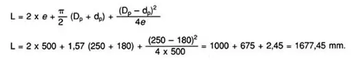
· From the table of the unified values in accordance with the regulations DIN 7753 of the lengths L, one finds that the closest value to ours is L = 1675mm